Introduction
Deep Brain Stimulation (DBS) is a neurosurgical therapy that involves the implantation of electrodes into subcortical structures to deliver electrical impulses, modulate abnormal neural activity, and alleviate aberrant symptoms. Originally developed to treat movement disorders,1 DBS has become an effective intervention for Parkinson’s Disease (PD),2 Essential tremor (ET),3 epilepsy,4 and dystonia.5 Extending its capability beyond movement disorders, DBS is now applied to psychiatric conditions including Obsessive-Compulsive Disorder (OCD)6 and, as investigational use, major depressive disorder.7
In DBS, identifying the optimal surgical targeting location is critical in achieving the best clinical outcomes across various disorders.8–13 To analyze and associate clinical improvements with stimulation locations, electrodes need to be reconstructed using dedicated neuroimaging pipelines. Lead-DBS is a widely-used, openly available software tool that facilitates this process.9 The software integrates advanced neuroimaging techniques with anatomical mapping to identify DBS electrode placement.
Despite the advancement of toolboxes such as Lead-DBS, accurate DBS electrode localization remains a semi-automated process that is dependent on user skill. A recent study by Lofredi et al. quantified the inter-user reliability of DBS localizations among six users using Lead-DBS to localize electrodes in 20 PD patients.14 The findings indicated that user-induced variability was minimal. However, in this study, users received formal training to ensure certainty in their reconstructions. Based on our internal experience over the years, in which many lab trainees became acquainted with Lead-DBS, we believe that Lead-DBS electrode localizations performed by entirely untrained novices are often inaccurate. This poses a problem and underscores the importance of formal training for tools like Lead-DBS. Ideally, new users would be trained in experienced labs, but this is not always possible and in turn leaves gaps in validation and consistency of electrode reconstructions. Though an open dataset with expert-localized annotations could be a valuable resource for trainees to practice and benchmark their skills, no such resource is available.
To address this gap, we provide a comprehensive open dataset for users to train on, which includes fully anonymized pre- and post-operative medical images from patients with various neurological disorders. Furthermore, we developed a training module within Lead-DBS that allows users to submit their results and automatically compare them with the ground truth localizations by an expert team. In addition to expert solutions, a larger peer-group of non-expert users localized the data, which made it possible to establish standard-deviations of localization inaccuracies. Upon submission of results, users will receive detailed graphical feedback on absolute difference from expert solutions and relative difference from non-expert solutions. By offering both the dataset and the training module, we aim to enable users to achieve greater precision in DBS electrode localization and enhance the effectiveness of DBS research.
Methods
IRB Approval and Data Sharing
The Institutional Review Board (IRB) of Brigham and Women’s Hospital, Boston, MA, USA approved public sharing of a completely anonymized dataset of patient data (Protocol #2022P001215). Given the secondary use of medical records data, the study was exempt from obtaining informed consent. This dataset consists of Magnetic Resonance Imaging (MRI) images acquired without implanted electrodes (before surgery) and Computed Tomography (CT) images with implanted electrodes (after surgery). According to IRB protocol, the dataset is available through the Open Science Foundation (OSF) for open download. Data may be used by the public to practice lead localizations, which could benefit future research studies by enabling scientists to practice and understand the non-clinical applications of DBS electrode localizations.
Training Dataset
Pre- and post-operative medical images from ten patients were retrieved from the Picture Archiving and Communication System (PACS) of Brigham and Women’s Hospital, automatically defaced, and stripped of any identifying metadata. They were assigned entirely random IDs, and any links to identifying information were permanently removed, making it impossible for the investigators to reestablish links to patient identities. Basic demographic data (such as age, gender or clinical improvements) were deliberately excluded to ensure full anonymization.
Electrode Reconstructions
To establish a ground truth of electrode reconstructions, a team of two experts and ten trained non-expert users localized electrodes in all ten patients. Authors AH and CN served as experts, each having previously localized over 1,000 electrodes. Their localization results were used to establish the ground truth coordinates and rotations for the training dataset. To ensure that their results were consistent with each other, we computed the difference in distance and angle for each electrode localization across the two solutions. For the purpose of this paper, we occasionally use the short-hand of ‘ground-truth’ to refer to these expert reconstructions. We must emphasize, that even the expert solutions do not necessarily represent a ground-truth solution in the stricter sense, which would only be obtainable using post-mortem histological confirmation.
Ten members of the Center for Brain Circuit Therapeutics, ranging from research assistants to postdoctoral fellows, who we refer to as non-experts, also performed localizations on the training dataset. Each non-expert user had substantial expertise with Lead-DBS but had carried out less than ~100-200 localizations. Results of non-experts were used to establish typical standard deviations in reconstruction results.
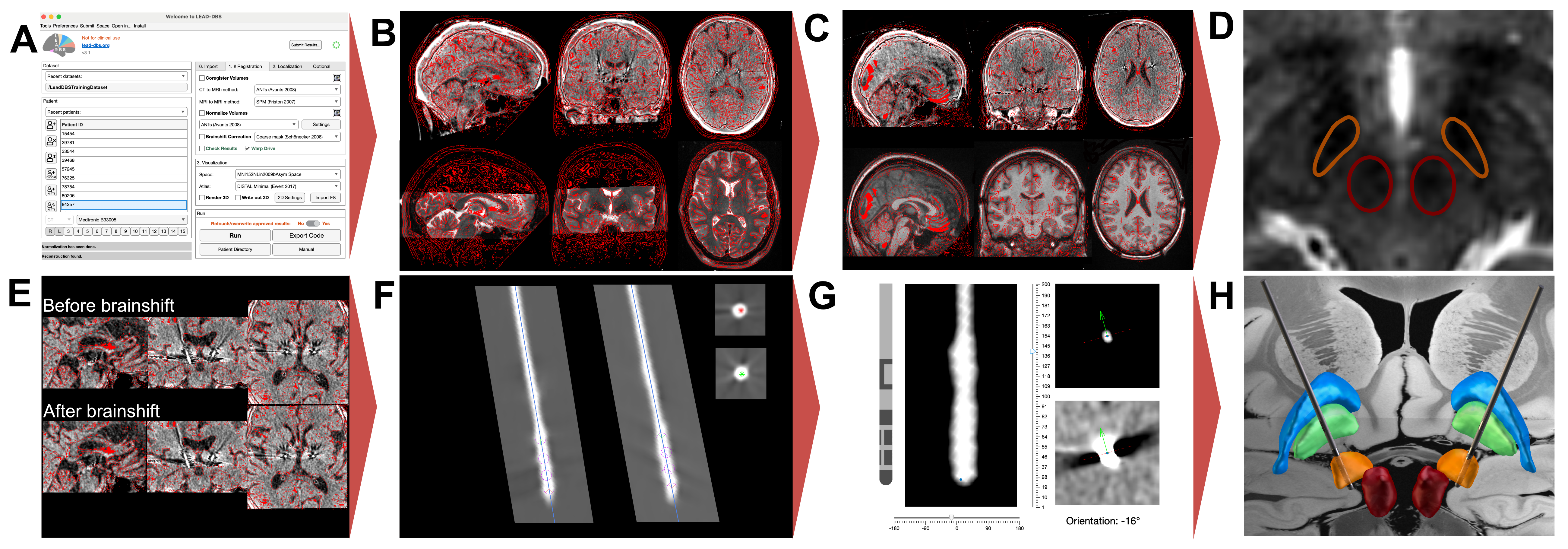
Figure 1 summarizes the Lead-DBS workflow that was carried out by each user and matches the default steps described in the associated methods paper.9 The process typically begins with importing patient images (Figure 1A), which are converted from DICOM to NIfTI format and renamed into the Brain Imaging Data Structure (BIDS15) standard. Due to anonymization efforts, this very first conversion step was carried out centrally and users were given the ‘base dataset’ of defaced NIfTI images in native patient space. These pre- and post-operative images were then co-registered to one another (Figure 1B). While Lead-DBS offers several co-registration algorithms for MR-MR and MR-CT co-registration, the default options are Statistical Parametric Mapping (SPM16) and Advanced Normalization Tools (ANTs17), respectively.

Users were free to choose the method most suitable for each patient imaging and to carry out registrations multiple times as long as they believe results were accurate. By default, the T1-weighted MRI serves as the ‘anchor modality’, i.e., images of other modalities are registered to this image. Following co-registration, volumes were spatially normalized to the ICBM 2009b nonlinear (Montreal Neurological Institute) space. By default, the SyN approach17 implemented in ANTs is applied with settings optimized for subcortical structures18 (Figure 1C). As with co-registrations, users were allowed to choose different methods that could be manually refined in the next step. Namely, after normalization, the WarpDrive tool19 was used to manually refine deformation fields to ensure precision of warps, especially around the target structure (Figure 1D). Users were asked to visually inspect and adjust the fit of atlas structures to patient-specific anatomy, ensuring precise registrations between electrodes and target structures. This step is critical for improving the accuracy of the normalization, especially in anatomically variable regions. The brain shift correction algorithm was applied next, which refines the co-registration between pre- and post-operative images based on subcortical masks which is helpful to reduce shifts introduced by pneumocephalus20 (Figure 1E). Users were then asked to ‘pre-localize’ electrodes using either the PaCER21 or TRAC/CORE22 algorithm and to subsequently manually refine localizations using the dedicated viewer (Figure 1F). Finally, users were asked to reconstruct directionality of segmented electrodes with the DiODe (Directionality Orientation Detection) tool23 as implemented in Lead-DBS,24 which facilitates this process based on electrode artifacts visible on CT scans (Figure 1G). Results could be visualized in 2D or 3D views (Figure 1H).
Comparing Electrode Reconstructions
For each user and electrode, two variables were obtained: the distance between the reconstructed electrode coordinates and the expert ground truth coordinates, and the difference between the reconstructed rotational angle and the expert ground truth angle.
Electrode positions may be defined by coordinates of two points, which Lead-DBS internally refers to as ‘markers’. The ‘head’ marker is defined as the midpoint of the first contact level (lowermost), whereas the ‘tail’ marker is the midpoint of the last electrode level (uppermost). To obtain a single metric of deviation across users, the Euclidean distances were measured between each user’s head and tail marker positions and the corresponding expert ground truth positions in template space.14 These head and tail distances were then averaged to provide an overall deviation metric.
The process of determining axial orientation of an electrode is implemented by use of a third reference marker, in Lead-DBS defined as the ‘y’ marker, which was used to compare its position with respect to the electrode direction. The y marker, orthogonally offset from the line that connects head and tail markers, can point in any given (rotational) direction. To quantify directional differences, the vector pointing from the head to the y marker was projected onto the XY-plane, and then normalized, allowing us to focus on direction relative to the patient’s head. This projection was used to calculate the rotational angle (measured in degrees) for each user, and then compared to the expert reference angle to determine rotational difference.
Standard deviations were calculated based on the deviations between the non-expert and (averaged) expert localizations across the training dataset. For each patient, Euclidean distances and rotational differences were measured. The standard deviations of these distances were computed to provide a metric for assessing localization consistency and difficulty across the dataset.
Results submission and feedback environment
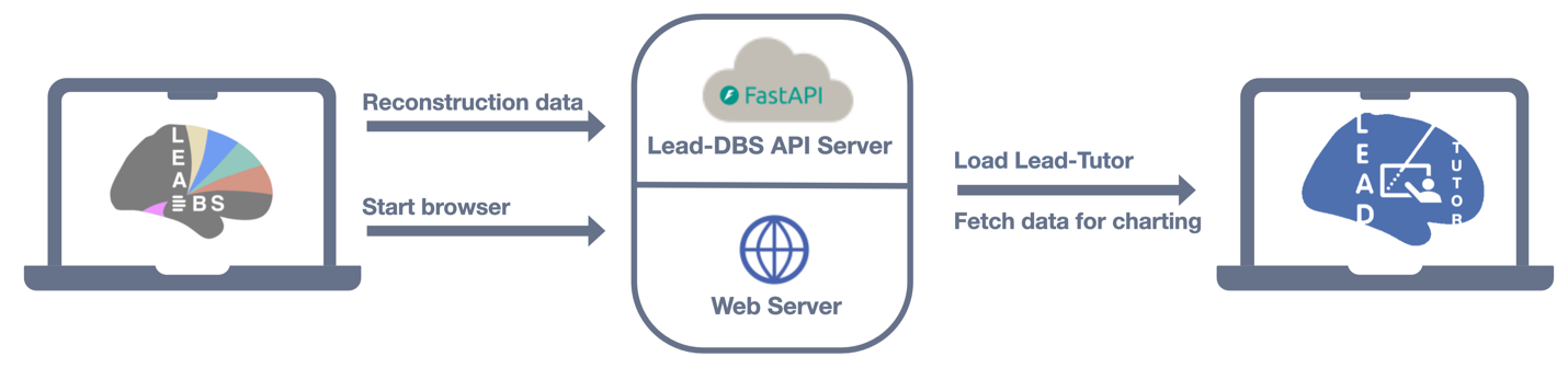
To allow users the ability to submit their localizations across the ten patients and compare them to ground-truth results established by experts, a webserver with an interface from Lead-DBS was built. Figure 2 outlines this framework. Upon submission of results, the head, tail and y markers are transmitted to the web server which then compares results to the ground truth and visualizes comparisons through a react (https://react.dev) platform. The backend of this architecture was built using Fast API (https://fastapi.tiangolo.com), which processes the reconstruction data and computes the differences in distance and orientation of the electrodes. The feedback includes detailed performance metrics, offering both individual comparisons across cases and group-level summaries.

Results
Dataset
Imaging data from 10 patients from Brigham and Women’s Hospital (Harvard Medical School, Boston, MA, USA) were included in the dataset. Of the patients, eight were diagnosed with Parkinson’s Disease, one with dystonia, and one with epilepsy. No additional information beyond the data reported in Table 1 was retrieved from medical records, and any links to patient identifiers were permanently destroyed. Critically, we deliberately included a small number of cases in which imaging was suboptimal to represent ‘challenging’ training cases.
All patients were bilaterally implanted with DBS electrodes. Three different types of electrodes from three manufacturers (Abbott, Boston Scientific, and Medtronic) were used. Six of the patients were implanted with Boston Scientific (Vercise Cartesia DB-2202), two with Medtronic (Sensight B33005), one with Medtronic (3387), and one with Abbott (Infinity 6172) electrodes (Table 1).
The dataset includes a range of pre-operative imaging modalities, including T1-weighted, T2-weighted, and FLAIR sequences. While some of these modalities may enhance anatomical visualization of specific structures or impact reconstruction accuracy, we deliberately chose a heterogeneous dataset to accustom users with differing input data during the training process.
Electrode localizations
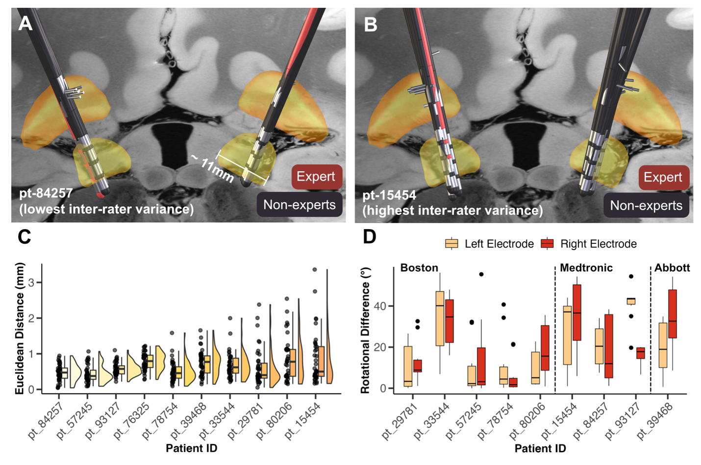
Localizations carried out by experts had an average distance of 0.37 mm between electrodes, and an average rotational difference of 4.68 degrees in standard stereotactic space. This minimal difference demonstrates the robustness of expert localizations, with independent agreement on both electrode position and orientation. We also evaluated the accuracy of electrode localizations performed by non-experts. Non-expert localized electrodes had an average distance of 0.66 mm from experts, and an average rotational difference of 20.31 degrees, which still shows robust agreement between results in the range that has been priorly reported (average difference of 0.72 mm as reported by Lofredi et al.14).
Figure 3 visualizes differences in reconstructions across individual patients. Panels A and B represent the electrode trajectories for two example patients, comparing expert (red) and non-expert (grey) localizations. Panels C and D show Euclidean distance and rotational difference between non-expert reconstructions and the average expert solutions. Patients are ordered by increasing variance, which was later used to order the dataset in terms of ‘difficulty’ in the now publicly available training dataset. Rotational discrepancies appeared more variable in some patients, indicating the challenges non-experts face in consistently aligning electrode orientations. Troubleshooting determining orientation of directional leads can found in this subsection of the lab manual: reconstruct orientation of directional leads.

Web Interface
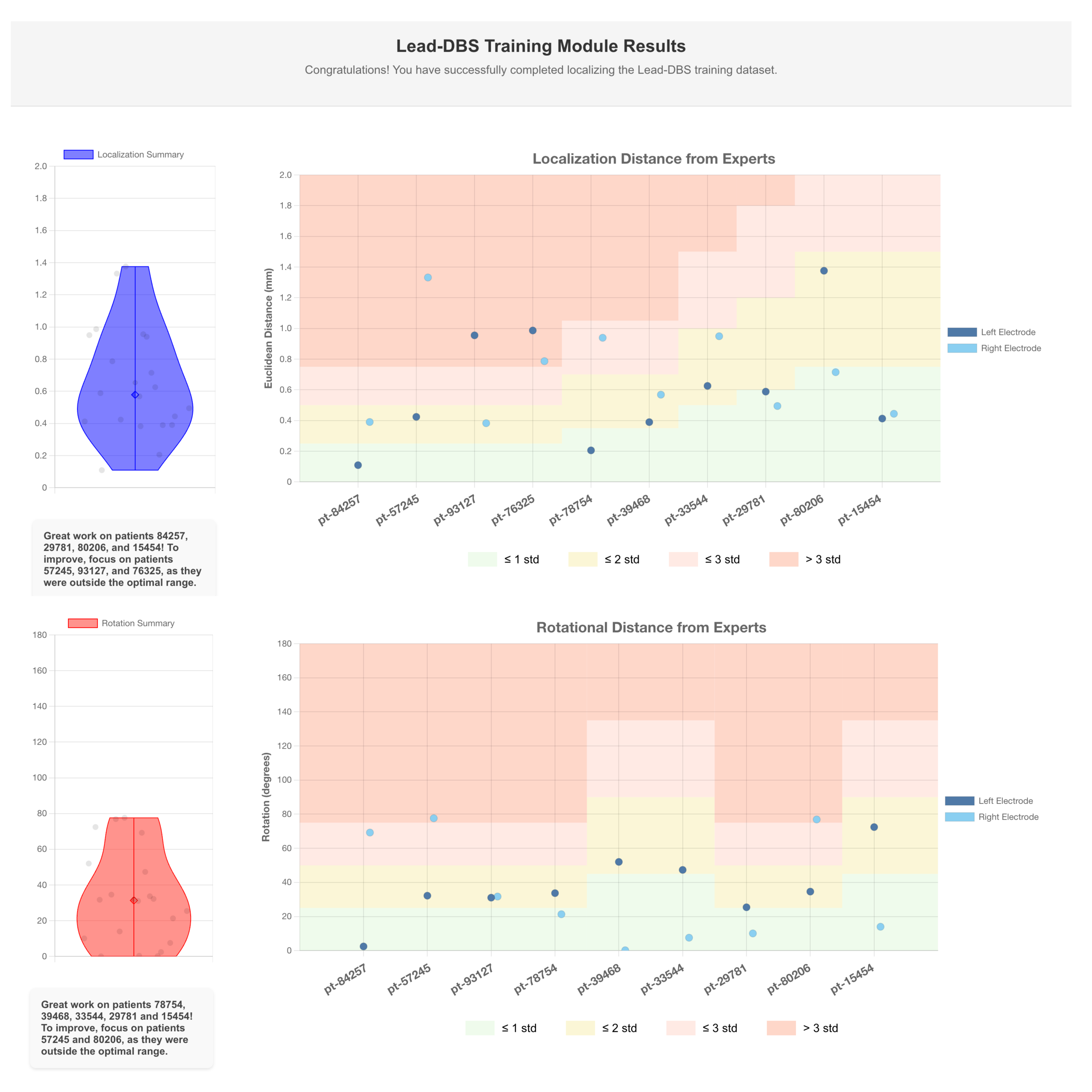
The data displayed in Figure 4 shows comparisons of electrode localizations and rotations as performed by a single user against expert-defined standards. The visualized results represent the performance of a skilled user; novice users may initially exhibit greater variability, which can be addressed through iterative practice supported by Lead-Tutor.

The feedback is automatically generated using the Lead-Tutor platform. The top panel indicates the Euclidean distance between the user and expert lead localizations. The bottom panel shows rotational distance between the orientations of user and expert lead localizations. The electrodes on the left and right sides are compared across the patients in the training dataset. The background color bands represent standard deviations derived from non-expert performance relative to experts.
These bands provide context for users to see how their localizations compare to other (trained but non-expert) users: green represents localizations that fall within one standard deviation of expert accuracy, yellow represents up to two standard deviations, and red indicates larger deviations. Standard deviation bands were calculated for each patient, since imaging quality in these varied, allowing for an increasing difficulty level within the dataset.
Discussion
Lead-Tutor is a community resource that may fill a critical gap in DBS research by providing an openly accessible dataset to acquire skills in electrode localization. Based on imaging from ten anonymized DBS cases, and a tool to self-test accuracy of electrode localizations, this resource allows researchers to refine their skills and ensure precision in electrode placement.
Accurate localization is fundamental to DBS therapy, as optimal electrode positioning directly correlates with patient outcomes.25 Similarly, accurate reconstructions of DBS electrodes are fundamental to creating meaningful representations in computer models and statistics across patients. By offering a structured means of self-study, Lead-Tutor supports broader access to these valuable skills.
One of the key contributions of this work is the provision of ground truth localizations performed by expert users, which serve as benchmarks for training. The additional inclusion of non-expert localizations may provide insights into the typical variability associated with electrode reconstructions, enabling trainees to gauge their own accuracy relative to experienced professionals. This is particularly relevant given the semi-automated nature of current DBS localization pipelines, where human intervention is still essential for achieving the highest level of precision. The average difference between experts and non-experts (0.66 mm, ~20 degrees) demonstrated in our study is encouraging, as it suggests that with proper training, users can approach high accuracy with errors in the magnitude of typical voxel sizes in clinical imaging data (~0.5-1 mm). The differences in position (0.37 mm) and rotation (~5 degrees) between the two expert users were even lower, leading to nearly identical localizations. This supports the idea that the expert average provided by the tool represents a meaningful ground truth for training.
While this manuscript primarily focuses on introducing a new dataset and self-testing tool for electrode localization via Lead-DBS, we acknowledge the value of offering additional user guidance. To address this need, we have curated extensive resources in the Lead-DBS User Guide, which includes detailed steps, troubleshooting advice, and practical techniques. Moreover, we provide further support through walkthrough videos and an active Slack community for direct assistance. We emphasize, however, that the present resource should not replace hands-on training with Lead-DBS or similar tools. Based on our experience, the process is complex, and training within a lab with established expertise is still the best practice. Nevertheless, this resource could serve as an additional building block or test scenario to objectively assess a user’s skill level in electrode localizations.
By making this dataset publicly available, we aim at supporting access to DBS imaging data. Open-source tools have historically driven the field of neuroscience forward. For instance, toolboxes such as Statistical Parametric Mapping (SPM),16 the FMRIB Software Library (FSL)26 or advanced normalization tools (ANTs)17 have revolutionized the analysis of functional brain imaging data and facilitated the development of other tools. Open datasets such as the Human Connectome Project,27 the Genomics Superstruct Project28 and the International Neuroimaging Data-sharing Initiative (INDI)29 have further pushed the field forward30 by allowing collaborations and analyses on data by researchers without access to neuroimaging data.31 Consisting of a broad array of features,9 Lead-DBS has emerged as a common tool21,32,33 in the realm of DBS. The inclusion of Lead-Tutor within this toolbox extends its functionality and provides a unique opportunity for users to learn electrode localization and compare their results with those of experts and other scientists. This resource also reduces the dependency on in-person training workshops, which can be both geographically and financially restrictive. By facilitating self-paced learning, Lead-Tutor makes DBS training more accessible to a broader audience, potentially leading to wider adoption of advanced DBS techniques and improved DBS research.
Bridging the gap between theoretical knowledge and practical skills, the training component is particularly valuable for neuroscience students, neurosurgical residents, and early-career researchers, who can gain experience with real-world data. By making high-quality data and training tools accessible to a broad audience, we hope to foster a collaborative environment that promotes excellence in electrode localization.
Data and Code Availability Statement
Lead-DBS is an open-source platform available for download on GitHub. We also provide additional open-access resources for learning how to use the tool: documentation of the Lead-DBS pipeline and troubleshooting, walkthrough videos showing the individual steps, and a Slack user channel for additional questions (https://communityinviter.com/apps/leadsuite/user-channel). The Lead-Tutor dataset can be found here: OSF.
Acknowledgements
A.H. was supported by the German Research Foundation (Deutsche Forschungsgemeinschaft, 424778381 – TRR 295), Deutsches Zentrum für Luft- und Raumfahrt (DynaSti grant within the EU Joint Programme Neurodegenerative Disease Research, JPND), the National Institutes of Health (R01MH130666, 1R01NS127892-01, 2R01 MH113929 & UM1NS132358) as well as the New Venture Fund (FFOR Seed Grant). A. S. and P. Z were supported by a scholarship from the Einstein Center for Neurosciences Berlin. B.H.B and L.L.G gratefully acknowledge support by the Prof. Dr. Klaus Thiemann Foundation (Parkinson Fellowship 2022 and 2023).
Conflicts of Interest
A.H. reports lecture fees for Boston Scientific and is a consultant for FxNeuromodulation and Abbott. All other authors report no conflicts of interest.